
An introduction for CCGT Designers, Engineers, and Project Managers
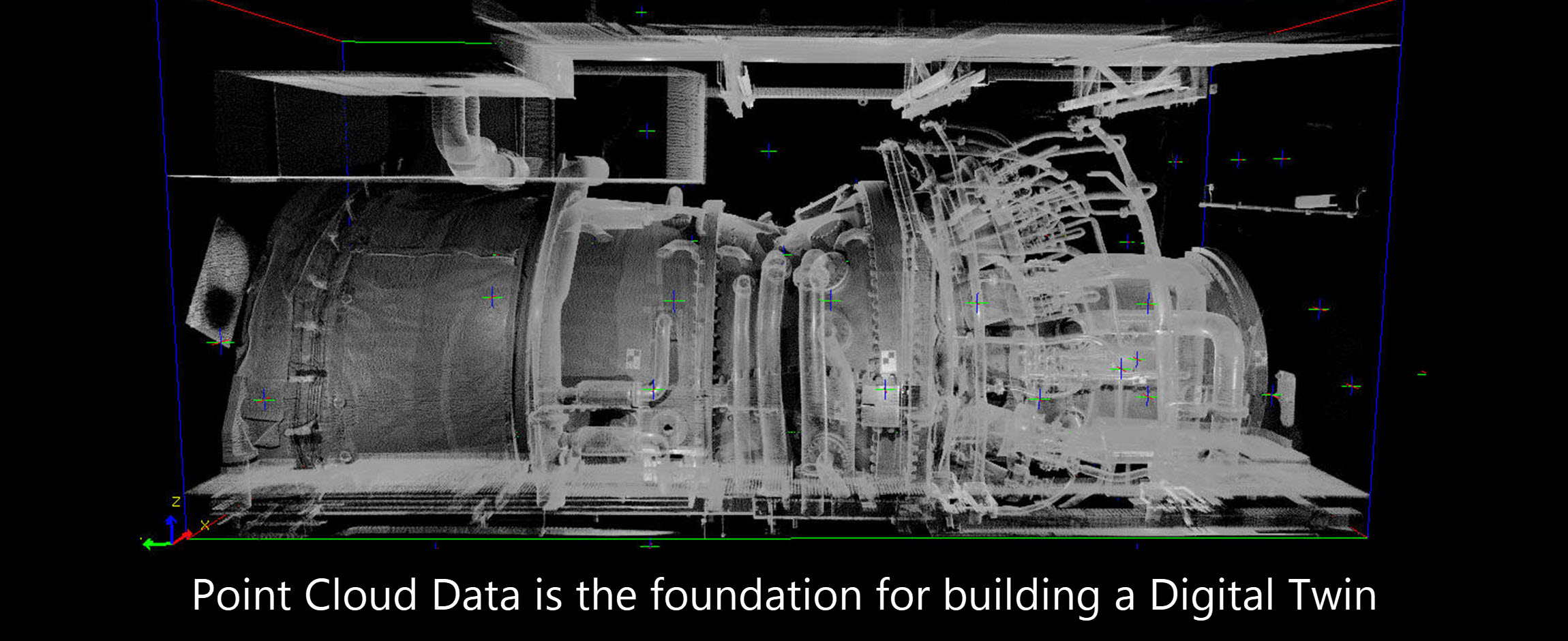
Laser Scanning is a non-contact, non-destructive technology that digitally captures the 3D shape of physical objects using a line of laser light. 3D laser scanners create “point clouds” of data from the surface of an object. As such, 3Dlaser scanning is a method to capture a physical object’s exact size and shape digitally to enable a 3-dimensional representation.
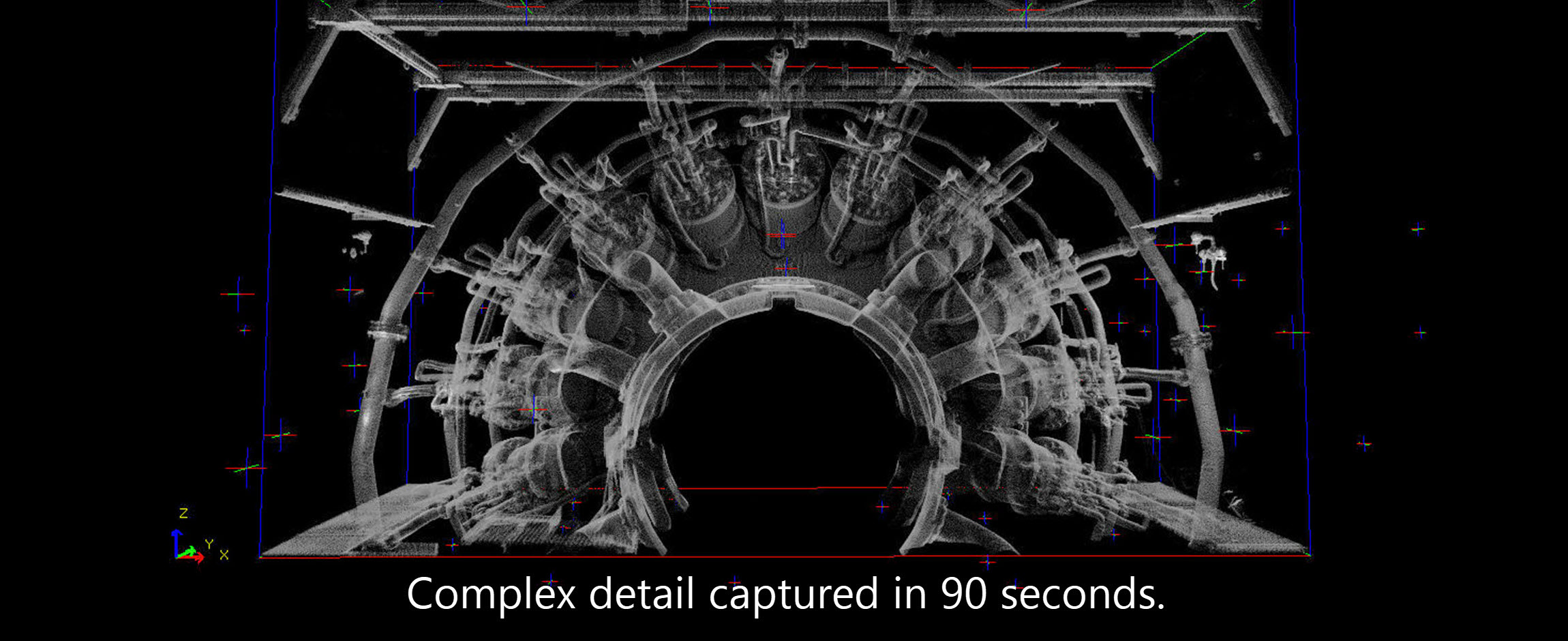
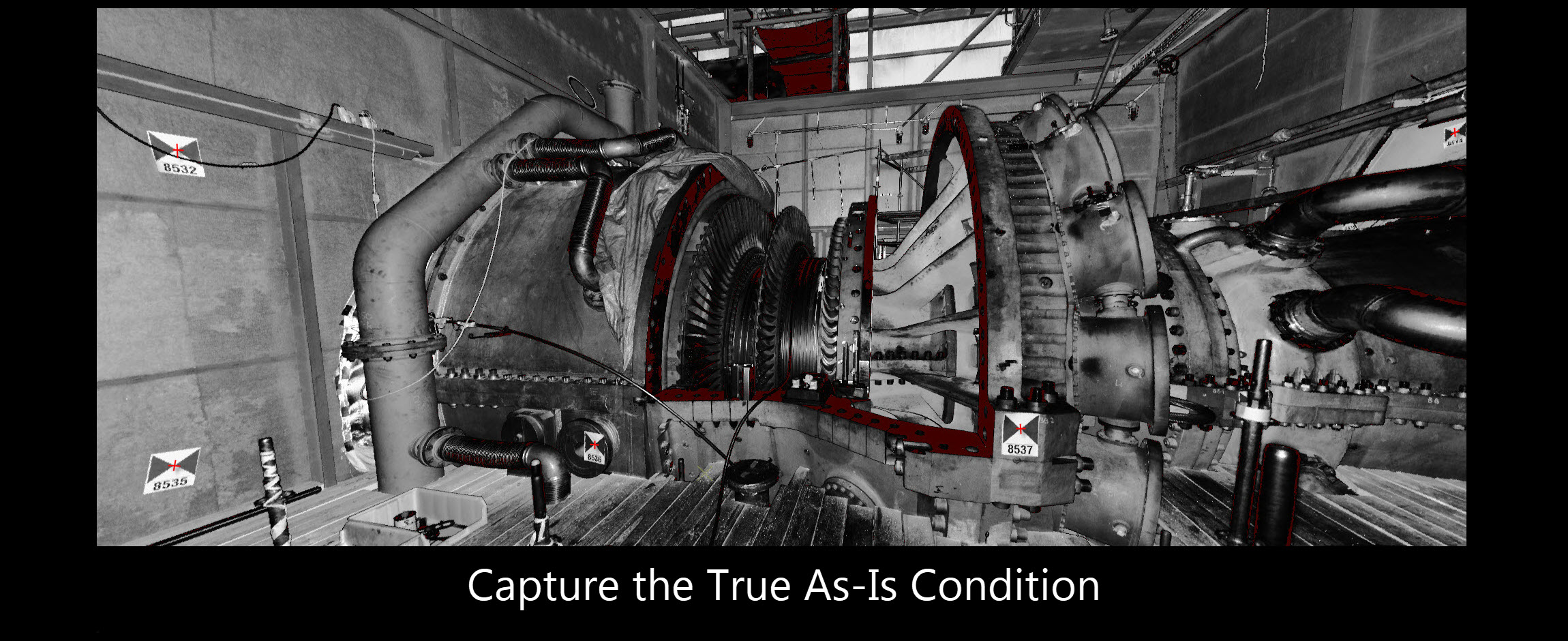
3D laser scanners measure fine details and capture free-form shapes to quickly generate highly accurate point clouds. 3D laser scanning is ideally suited to the measurement and inspection of contoured surfaces and complex assemblies which require massive amounts of data for their accurate description making laser scanning an important tool for capturing the as-built characteristics of a gas turbine power plant.
A 3D laser scanner consists of a signal source (laser) that is directed to the object under evaluation, sensors which receive a reflected signal from the object and software to collect the sensor data and calculate measured points in space. The laser probe projects a line of laser light onto an objects surface while 2 sensor receivers continuously record the changing distance and shape of the laser line in three dimensions (XYZ) as it sweeps along the object. The shape of the object appears as millions of points called a “point cloud” as the laser moves around capturing the entire surface shape of the object. The process is very fast, gathering up to 1,000,000 points per second and yields precise measurements.
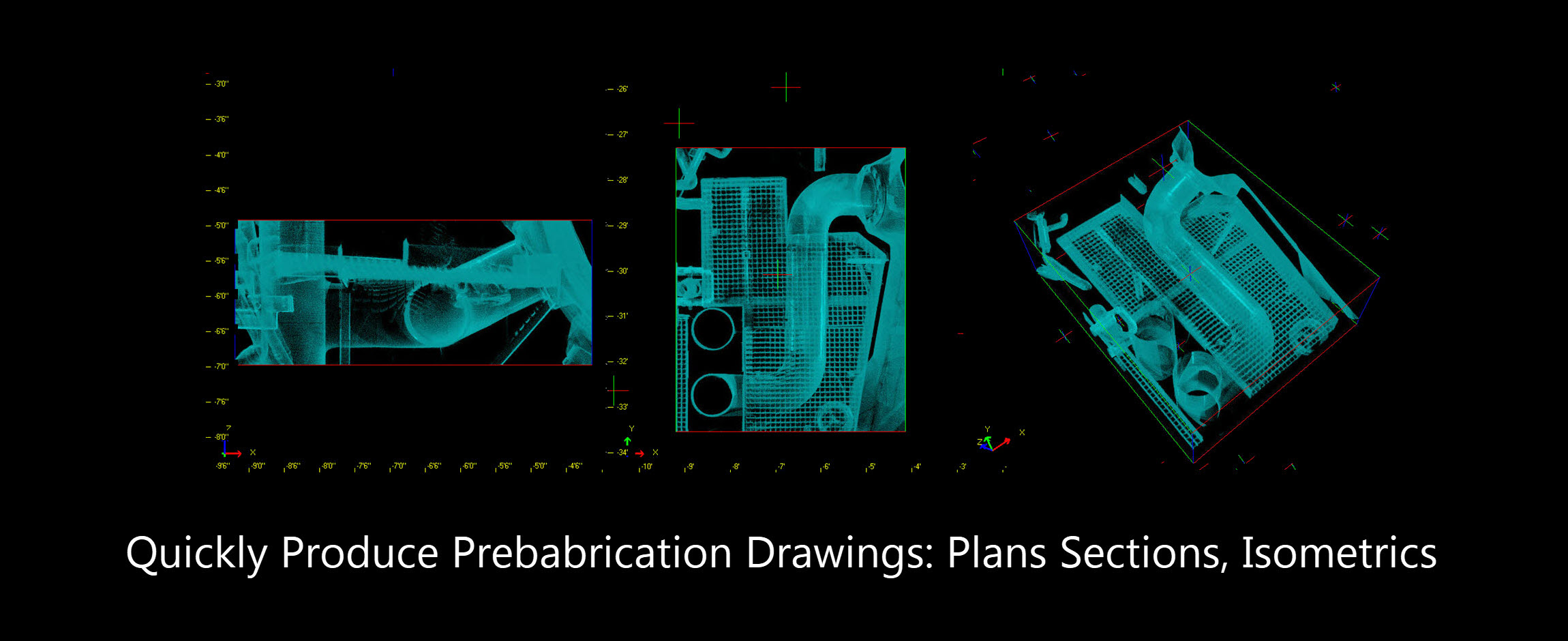
After the point cloud data files are created, they are registered and merged into one three-dimensional representation of the object and post-processed with various software packages suitable for a specific application.
The scope of the turbine upgrade or modification will dictate the scope of the Field Laser Scan. Any combination of the following typical scan areas may be required for the requisite modeling. Additional areas may be defined as required to accommodate design requirements.

Project Example:
For the Starting System, the collection site data would be:
• Distance between Stating system and enclosure walls
• Fitting of the Hydraulic Ratchet, SSS Clutch and Torque Converter
• Diesel, Lube Oil, Cooling water Piping around Starting Motor.
• Clearance distances in the mounting of the proposed starting motor compared to the existing.
• Any piping or mounting interference across the surroundings of the Starting System.
Other systems that are affected by the Starting System Modifications will be also considered in the Laser Scanning modeling:
• Cool Water System
• Lube oil System
• Atomizing System
Benefits
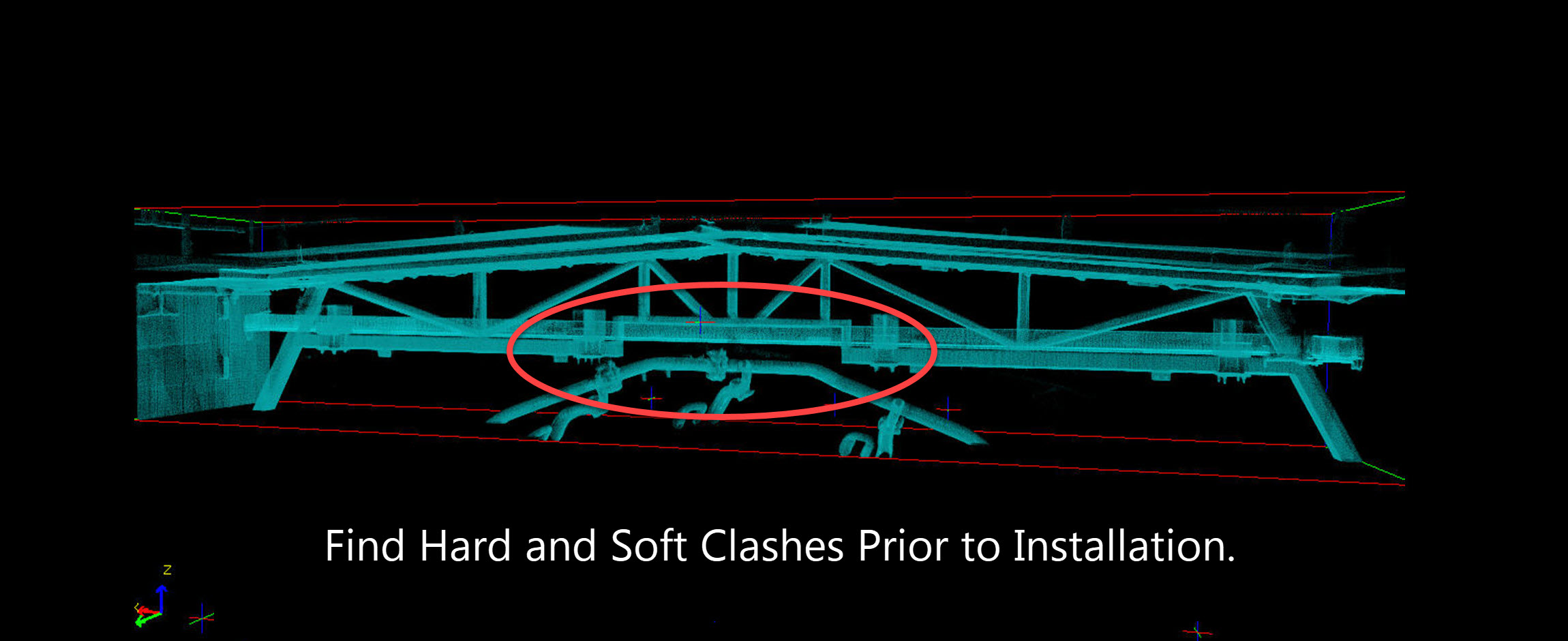
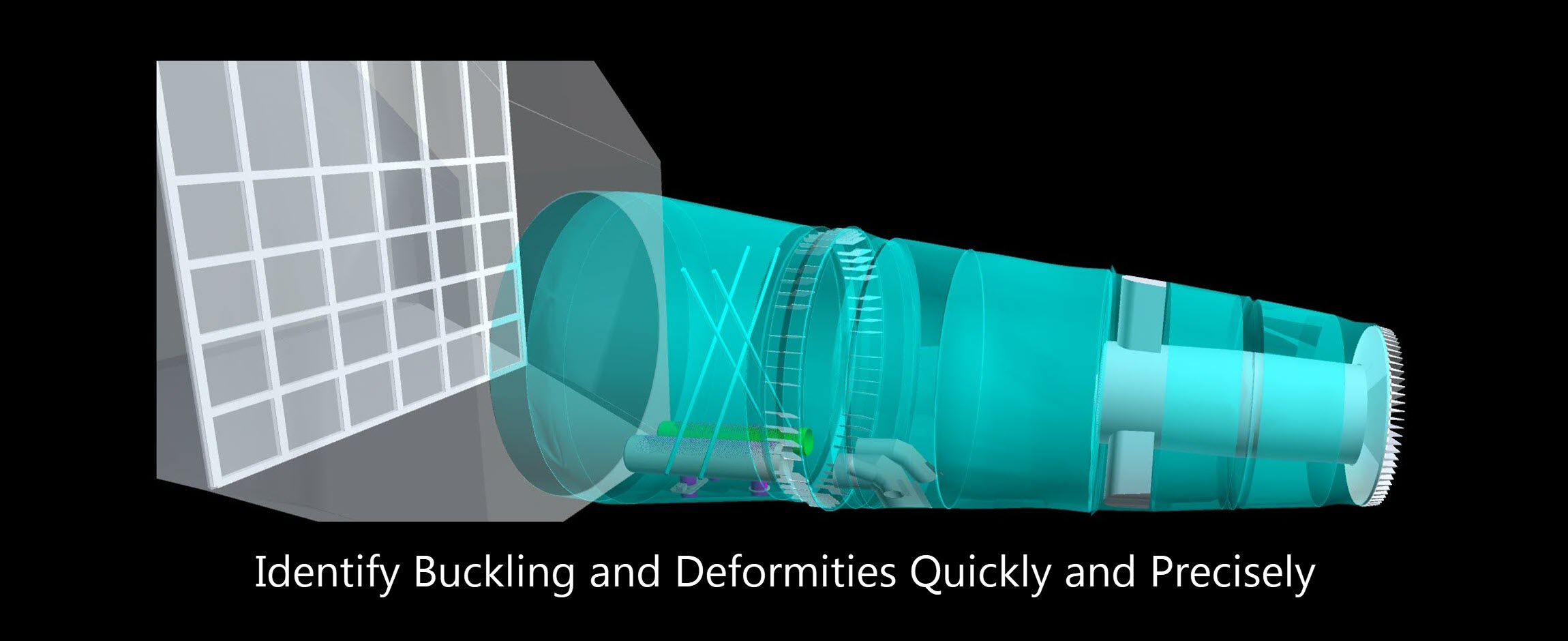
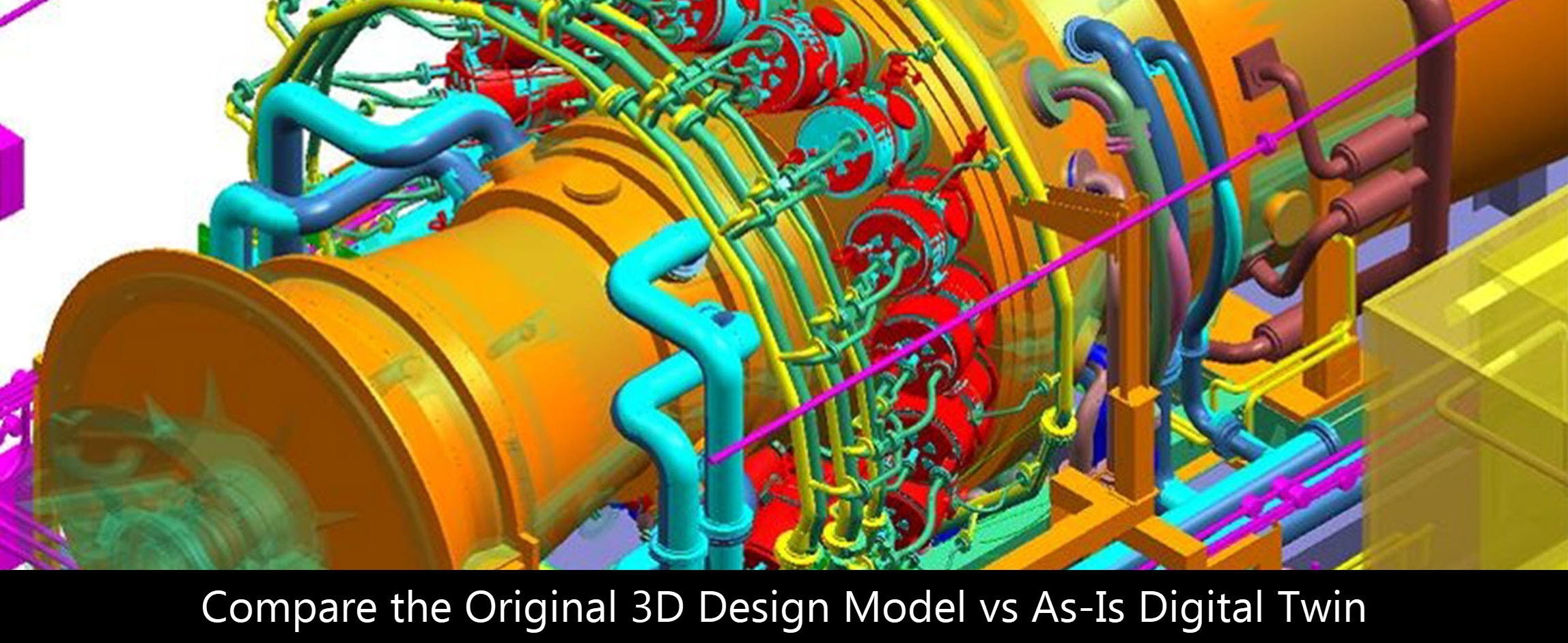
Laser scanning is a fast, accurate and automated technology to acquire 3D digtal data for engineering and design evaluation. Using specialized software, the point cloud data is used to create digital Twin 3D CAD models. The 3D CAD model enables a precise reproduction of the scanned object or geometry to facilitate assessment of the as-built plant/unit configuration.
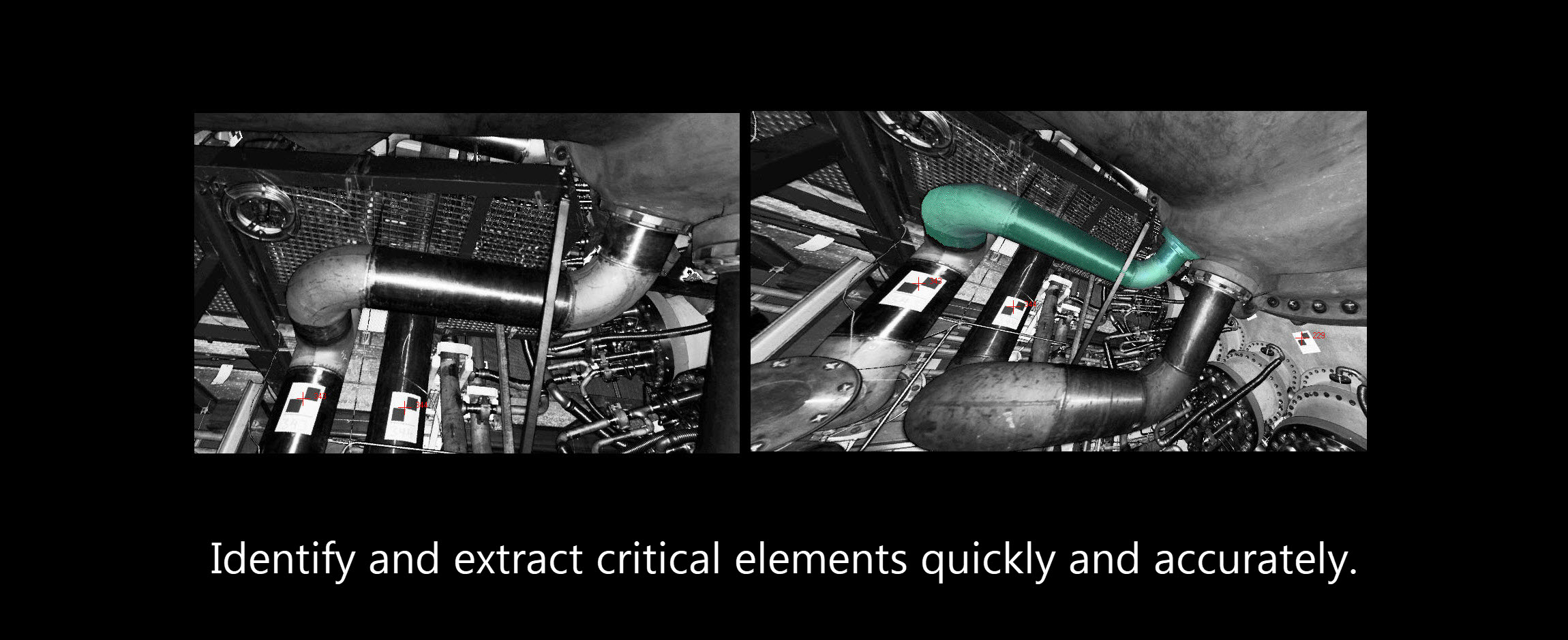
The following pictures are showing some examples of the models made with the information collected during the laser scan.
Site Information
Please Note: The laser does NOT trip or damage any sensors, and the laser light is eye safe.
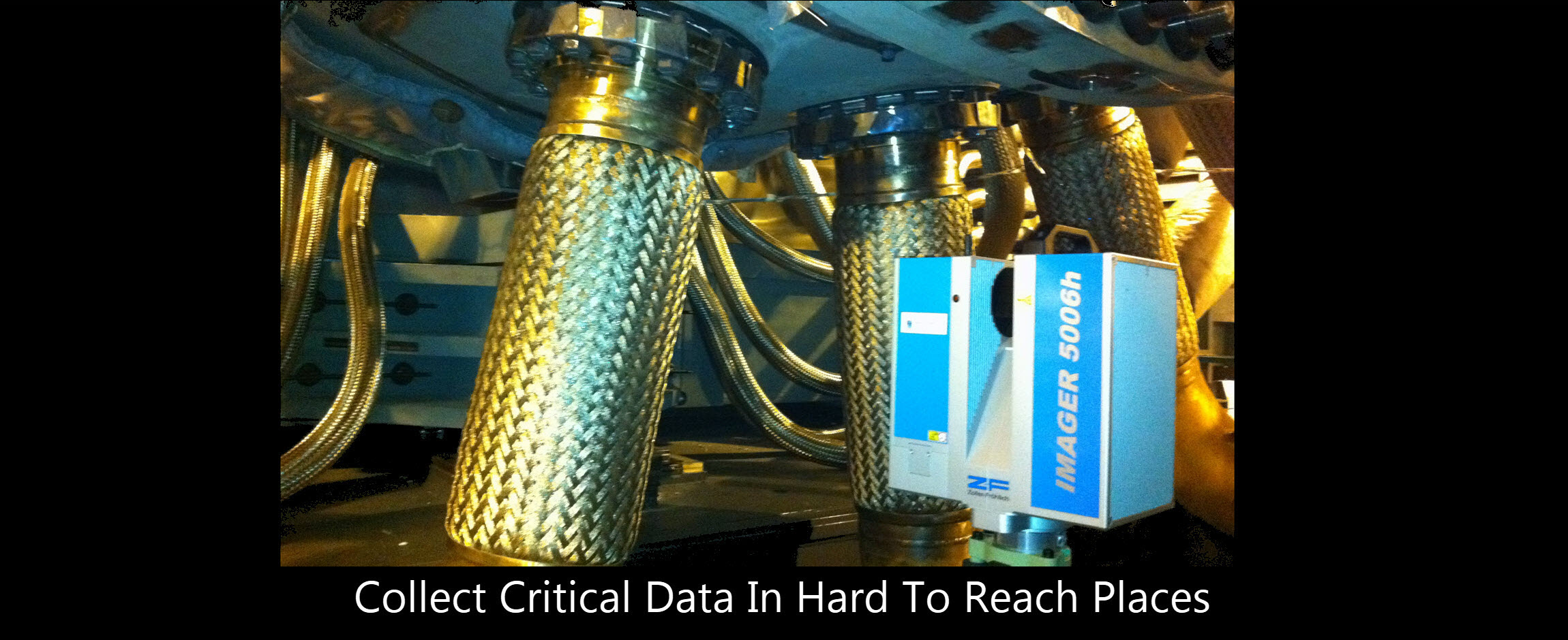
The laser scanning equipment and survey instruments are transported to site and mounted and operated by qualified personnel. Some additional help may be requested from the customer in providing floodlighting in low light areas for safety and ease of movement. Additional help my be requested in removing covers and lifting grating for complete access to critical equipment in order to ensure 100% data capture.
To assist in defining an accurate SOW, the as-built plant arrangement (PA) drawing and any photographs of detail and/or areas related to the specific upgrade are helpful.
In conjunction with the issuance of a purchase order, site is requested to provide information related to EHS and PPE requirements as well as any permits that would be required for the visiting personnel.
As the scanning process may include interior compartment areas, including but not limited to turbine, fuel gas, and lube oil enclosures, it is required that these areas be made accessible for entry to correspond with the pre-arranged scheduling of the scan. The scan requires the unit(s) to be shut down and cooled prior to scanning.
In general, scanning the interior of the Turbine Compartment, Accessory Compartment and Fuel Gas Compartment would take a total of approximately 8 hours.
• Turbine Compartment Interior – 4 hours
• Accessory Compartment Interior – 2 hours
• Liquid Fuel Compartment Interior – 2 hours
Schedule & Cost
Depending on the CM&U project type and SOW, only 1 or 2 survey personnel would be required to perform the laser scan survey, over a 1- or 2-day period.
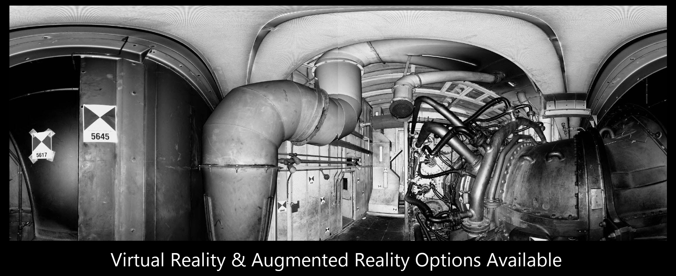
Registered scan cloud data in the form of a Visual Database is typically delivered within 72hrs of leaving the site. The Digital Twin 3D Model is delivered between 10 and 15 business days following visual database delivery.
The price quoted include all the on-site functions, office processing, and Digital Twin 3D modeling as well as the travel, lodging, insurance and equipment expenses.
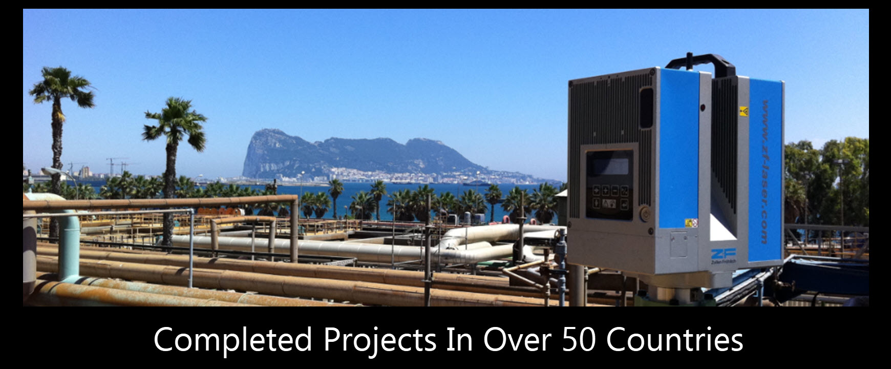
Logistics
Texas Surveys has worked in over 50 countries on 5 continents. 1-2 days round trip travel is needed for projects within North America. 3-4 days roundtrip travel is needed for Europe, East Asia and South America. And 4 – 5 days round trip travel for hard to reach locations in Middle East, Africa, China and Russia. For countries requiring visas and security details, adequate time should be allowed to apply, process and schedule such activities. Carnets are used to hand carry equipment around the world, so shipping is not required.